Tilt Steering Column Loose?
by George Nenadovich
A common problem with GM/Saginaw tilt steering columns is the upper
pivoting section becomes "loose" from the lower section causing
wobble or excessive play in the column. The only way to solve this problem
is to completely disassemble the column and tighten the four mounting screws
that hold the pivoting section base to the lower column section.
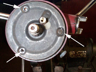 Here is a column shift tilt from a 75 Monte Carlo. After
removing the steering wheel this is the view you will have. For a proper
rebuild, you should remove the column from the car. Remove the 3 screws
from the lock plate cover plate indicated by arrows. Two are already removed
in this pic.
Here is a column shift tilt from a 75 Monte Carlo. After
removing the steering wheel this is the view you will have. For a proper
rebuild, you should remove the column from the car. Remove the 3 screws
from the lock plate cover plate indicated by arrows. Two are already removed
in this pic.
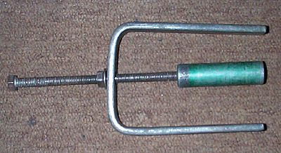 This is the steering column lock plate removal tool. If you
do frequent column work, you should buy one. You can also get these or similar
ones from auto stores that have tool loan programs.
This is the steering column lock plate removal tool. If you
do frequent column work, you should buy one. You can also get these or similar
ones from auto stores that have tool loan programs.
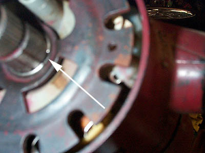 This is the view after the cover plate is removed. The arrow
indicates the snap/retaining ring that needs to be removed in order to disassemble
the rest of the column.
This is the view after the cover plate is removed. The arrow
indicates the snap/retaining ring that needs to be removed in order to disassemble
the rest of the column.
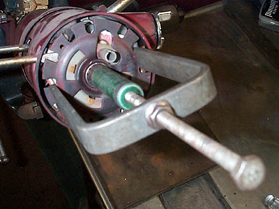 Tool threads onto the steering wheel stud. Arms force the
lock plate down as you turn the nut that sits on top of the arms.
Tool threads onto the steering wheel stud. Arms force the
lock plate down as you turn the nut that sits on top of the arms.
 The tool has pressed down the plate about 1/8" and you
can see the groove where the ring resides. I have moved the ring up using
two small flat blade screwdrivers to walk the ring up the stem. Remove the
pressure on the lock plate by loosening the tool. This will bring up the
ring and let you remove the lock plate.
The tool has pressed down the plate about 1/8" and you
can see the groove where the ring resides. I have moved the ring up using
two small flat blade screwdrivers to walk the ring up the stem. Remove the
pressure on the lock plate by loosening the tool. This will bring up the
ring and let you remove the lock plate.
 With the lock plate and the turn signal disc removed, you
can see the turn signal mechanism. The 3 arrows starting at 1 o'clock and
going clockwise hold the turn signal assembly to the steering column upper
section. The last screw holds the turn signal arm to the assembly. The turn
signal screw has slightly different threads than the other three so don't
get them mixed. Don't forget to remove the hazard flasher knob.
With the lock plate and the turn signal disc removed, you
can see the turn signal mechanism. The 3 arrows starting at 1 o'clock and
going clockwise hold the turn signal assembly to the steering column upper
section. The last screw holds the turn signal arm to the assembly. The turn
signal screw has slightly different threads than the other three so don't
get them mixed. Don't forget to remove the hazard flasher knob.
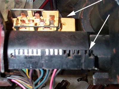 The lower arrow shows the factory "harmonica" connector
for the turn signal mechanism. Simply slide this up and it will come off
the retaining clip. THe upper arrow indicates the ignition switch. For tilt
columns, the orientation is 180 degrees different than non-tilt columns.
So, when changing from a non-tilt to tilt, you will have to rotate the wire
plug for the switch 180 degrees.
The lower arrow shows the factory "harmonica" connector
for the turn signal mechanism. Simply slide this up and it will come off
the retaining clip. THe upper arrow indicates the ignition switch. For tilt
columns, the orientation is 180 degrees different than non-tilt columns.
So, when changing from a non-tilt to tilt, you will have to rotate the wire
plug for the switch 180 degrees.
 This shows the harmonica connector removed from the column.
 This is the steering column support bracket. Use a 1/2"
socket to remove all 4 screws.
This is the steering column support bracket. Use a 1/2"
socket to remove all 4 screws.
 This is the reason you need to remove the support. You need
to access the turn signal wiring loom and remove it from the column. Note
its installed position so you can replace it in the same position.
This is the reason you need to remove the support. You need
to access the turn signal wiring loom and remove it from the column. Note
its installed position so you can replace it in the same position.
 Here is the loom removed from the column. Notice factory
overspray. You can now slide the turn signal assembly from the column. You
will need to make the harmonica connector slide up the column and as your
other hand gently pulls on the assembly. Use a long flat blade screwdriver
to guide the harmonica connector completely out. It will take several tries
but it can be done.
Here is the loom removed from the column. Notice factory
overspray. You can now slide the turn signal assembly from the column. You
will need to make the harmonica connector slide up the column and as your
other hand gently pulls on the assembly. Use a long flat blade screwdriver
to guide the harmonica connector completely out. It will take several tries
but it can be done.
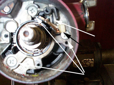 With the turn signal assembly removed, you will see the three
large Phillips screws to be removed so the upper steering column collar
can be removed from the column. The white single arrow indicates the key
cylinder tang that needs to be depressed in order to slide the key cylinder
from the column. On some of the 69-72 versions the tab can be covered by
flashing and you will need to use a small screwdriver to break the flashing
to access the tang. The black arrow indicates the turn signal contacts and
can be removed after the key cylinder. It is an easy piece to break so take
you time to remove it along with the small black spring that holds it in
place.
With the turn signal assembly removed, you will see the three
large Phillips screws to be removed so the upper steering column collar
can be removed from the column. The white single arrow indicates the key
cylinder tang that needs to be depressed in order to slide the key cylinder
from the column. On some of the 69-72 versions the tab can be covered by
flashing and you will need to use a small screwdriver to break the flashing
to access the tang. The black arrow indicates the turn signal contacts and
can be removed after the key cylinder. It is an easy piece to break so take
you time to remove it along with the small black spring that holds it in
place.
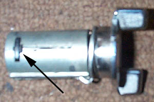 Arrow indicates the same tang as in previous pic
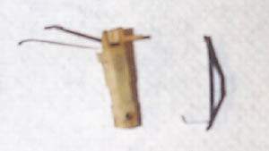 This is the horn and key signal contact set. Spring only
goes on one way on plastic housing.
This is the horn and key signal contact set. Spring only
goes on one way on plastic housing.
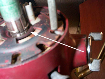
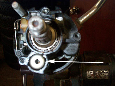 Arrow indicates the "pop-up" spring for the tilt
mechanism. Use a Phillips screwdriver to press down and rotate the cap counterclockwise
to remove. Gently ease up on cap slowly so spring does not fly out.
Arrow indicates the "pop-up" spring for the tilt
mechanism. Use a Phillips screwdriver to press down and rotate the cap counterclockwise
to remove. Gently ease up on cap slowly so spring does not fly out.
 This is the pop spring removed with cap and base pin still
inside the spring. Notice cap has tangs to hold it in place inside column.
This is the pop spring removed with cap and base pin still
inside the spring. Notice cap has tangs to hold it in place inside column.
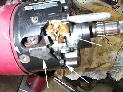 Now you will need to disassemble the lock cylinder interface.
The lower arrow indicates the 1/4" hex head screw holding the lock
plate pin spring. The upper arrow shows the snap ring that needs to be removed
from the gear that engages the rack below. The second arrow from the left
shows the tilt lever guide plate and needs to be removed. It easily slides
out. The arrow on the far left, is the pivot pin. More info on this below.
Now you will need to disassemble the lock cylinder interface.
The lower arrow indicates the 1/4" hex head screw holding the lock
plate pin spring. The upper arrow shows the snap ring that needs to be removed
from the gear that engages the rack below. The second arrow from the left
shows the tilt lever guide plate and needs to be removed. It easily slides
out. The arrow on the far left, is the pivot pin. More info on this below.
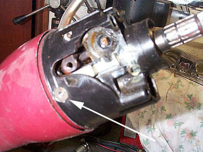
 Here is the same side view but a different angle. Arrow indicates
screw that needs to be removed. Notice the steering wheel nut threads in
this pic. These are 9/16-18 threads. Use a die if these are mushroomed due
to someone using a hammer to tap down on stem to remove the steering wheel
instead of using a steering wheel puller.
Here is the same side view but a different angle. Arrow indicates
screw that needs to be removed. Notice the steering wheel nut threads in
this pic. These are 9/16-18 threads. Use a die if these are mushroomed due
to someone using a hammer to tap down on stem to remove the steering wheel
instead of using a steering wheel puller.
 With gear, spring and lock pin removed, you will need to
remove the pivot pins.
With gear, spring and lock pin removed, you will need to
remove the pivot pins.
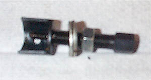 This is the pivot pin removal tool for Saginaw columns. This
is a must to remove the pins. Can be purchased from auto tool stores as
well as www.harborfreight.com
This is the pivot pin removal tool for Saginaw columns. This
is a must to remove the pins. Can be purchased from auto tool stores as
well as www.harborfreight.com
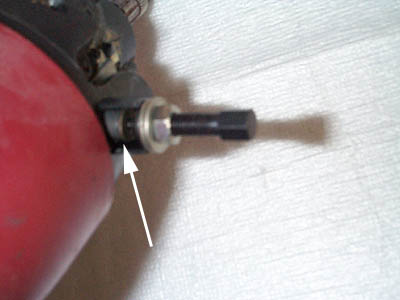 Simply screw tool into pivot pin and then tighten large 1/2"
nut. As you can see in the pic, the pin is about 1/4" out. Repeat for
the other side.
Simply screw tool into pivot pin and then tighten large 1/2"
nut. As you can see in the pic, the pin is about 1/4" out. Repeat for
the other side.
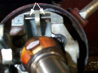 Arrows indicate the bars that tilt collar engages. Use the
tilt lever and pull it forward. Lift the collar as you pull on the tilt
lever and the column section will unhook from these bars.
Arrows indicate the bars that tilt collar engages. Use the
tilt lever and pull it forward. Lift the collar as you pull on the tilt
lever and the column section will unhook from these bars.
 These are the two levers that hold onto the pins.
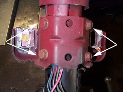
 This is the rack that the plastic ignition gear engages.
Left arrow shows a common area where these can break which will prevent
the key from starting the car. The right arrow shows an area to be greased.
This is the rack that the plastic ignition gear engages.
Left arrow shows a common area where these can break which will prevent
the key from starting the car. The right arrow shows an area to be greased.
 Same item but with small guide spring shown. Make sure you
don't loose this spring. The large area in the center of the rack slides
on the left pivot pin. Notice orientation of the rack so you can replace
the spring in the same position.
Same item but with small guide spring shown. Make sure you
don't loose this spring. The large area in the center of the rack slides
on the left pivot pin. Notice orientation of the rack so you can replace
the spring in the same position.
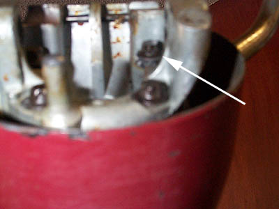 AHA!!!!!! This is the problem. Notice how
this screw is about 1/8" up from the base pivot material. There are
four total and you can only see three in this pic. The fourth is also about
1/8" up and needs to be tightened. To permanently fix this problem
clean the threads and then apply some Loc-tite thread locker. Tighten all
four screws using an E8 Torx socket.
AHA!!!!!! This is the problem. Notice how
this screw is about 1/8" up from the base pivot material. There are
four total and you can only see three in this pic. The fourth is also about
1/8" up and needs to be tightened. To permanently fix this problem
clean the threads and then apply some Loc-tite thread locker. Tighten all
four screws using an E8 Torx socket.
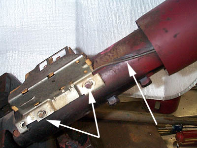 Right arrow indicates the rod that connects the rack and
the ignition switch. The other two arrows indicate the small 5/16"
screws that hold the ignition switch to the column. The switch has slotted
holes so there is a small amount of adjustment if needed.
Right arrow indicates the rod that connects the rack and
the ignition switch. The other two arrows indicate the small 5/16"
screws that hold the ignition switch to the column. The switch has slotted
holes so there is a small amount of adjustment if needed.
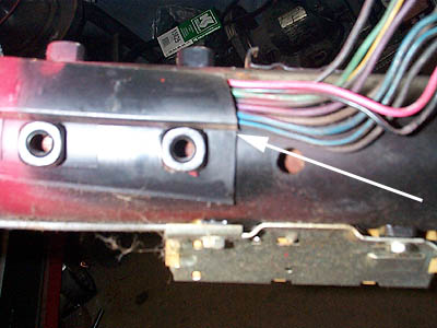
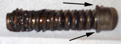
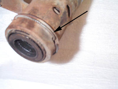 This is the engine side of the column. Remove the retaining
ring indicated by the arrow to remove retaining collar so you can access
the lower bearing.
This is the engine side of the column. Remove the retaining
ring indicated by the arrow to remove retaining collar so you can access
the lower bearing.
 Use a small screwdriver to gently tap down the direction
of the arrow to remove the bearing.
Use a small screwdriver to gently tap down the direction
of the arrow to remove the bearing.
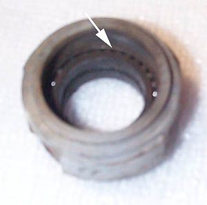 Bearing is removed from the column. Hard to notice in this
pic but the bearings are "bone dry" and need to be greased. Use
a grease needle in a grease gun to pack the bearings.
Bearing is removed from the column. Hard to notice in this
pic but the bearings are "bone dry" and need to be greased. Use
a grease needle in a grease gun to pack the bearings.
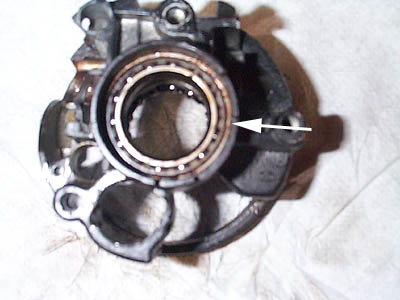 This is the upper column section. Notice bearings here are
also bone dry. Use the grease needle again.
This is the upper column section. Notice bearings here are
also bone dry. Use the grease needle again.
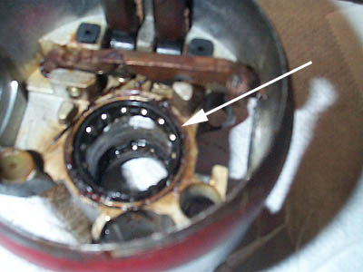 Here is the flip side of the same piece. Lower bearings are
also dry. Grease them too.
Here is the flip side of the same piece. Lower bearings are
also dry. Grease them too.
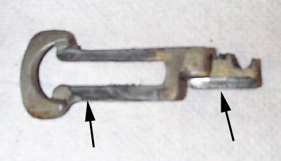
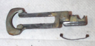
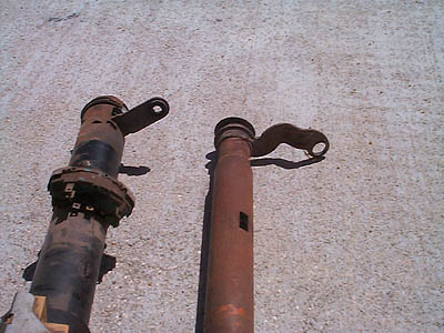 Here is a comparison of the 73-77 (left) column lock out
arm compared to the 69-72 on the right. The 73-75 A-body columns will work
in the 69-72 A-body models but have the different arm. The 76-77 will also
work but many parts were changed inside so you have to swap out the column
as a unit and I believe key cylinders are different for 76-77 models. You
will have to have the key cylinder remade to your existing key (you can
not install your original key cylinder(69-75) in the 76-77 columns.
Here is a comparison of the 73-77 (left) column lock out
arm compared to the 69-72 on the right. The 73-75 A-body columns will work
in the 69-72 A-body models but have the different arm. The 76-77 will also
work but many parts were changed inside so you have to swap out the column
as a unit and I believe key cylinders are different for 76-77 models. You
will have to have the key cylinder remade to your existing key (you can
not install your original key cylinder(69-75) in the 76-77 columns.
Reassemble column in reverse order as shown in pics. Expect to take
at least 1 hour to do a complete teardown and rebuild. If you are painting
the column this will add to the time required.