Most 1965-72 A-bodies (Skylark, Cutlass, Chevelle, LeMans and 1970-2 Monte Carlo & Grand Prix) came with drum brakes and are not very desirable. Drum brakes do not work as well as disc brakes and were phased out by GM beginning in 1973. In that year, all A-body cars came with disc brakes standard. Unfortunately, the 1973-77 A-body disc brake set-ups will not work on the 1965-72 cars. So, you will need to find a 1965-72 A-body with disc brakes. They are usually found on higher end models such as GS, 442, GTO, SS and some 4 doors and wagons. Most of the time the cars that you can find in salvage yards with disc brakes will be 4 dr hardtops and wagons. Most of these models have disc brakes. Also, all 1970-2 Monte Carlo and Grand Prix models have disc brakes as standard equipment.
As an option, you can use the 1972-81 F-body (Camaro, Trans AM, Firebird) front disc brakes on the 1965-72 A-body cars with an adapter kit available from Hotchkis Performance. The kit runs about $390 and can be purchased from JEGS at 1-800-345-4545, kit #515-1103.
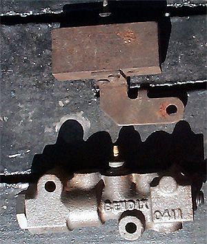
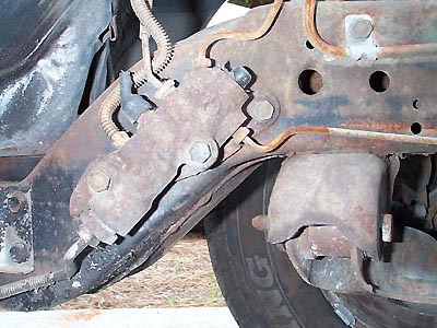
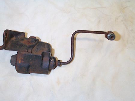
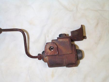
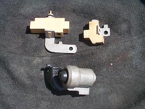
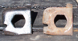
The most important part to get is the spindle with backing plate. Also, make sure to get the proportioning valve which is located on the frame rail directly below the master cylinder. They are not available as rebuilts or at auto parts stores. All other disc brake parts are available as rebuilt or new: brake hoses, brake calipers, rotors, pads, master cylinder. New banjo bolts are available from NAPA #82701 for $5 each. See the pictures below for more help.
If You Should Experience Any Of The Following Conditions While Bleeding The Brakes:
NO FLUID FLOW TO EITHER FRONT OR REAR BRAKES.
LIMITED FLUID FLOW TO EITHER FRONT OR REAR BRAKES.
NO OR LOW PEDAL.
BRAKE WARNING LIGHT STAYS ON.
BRAKE WARNING LIGHT COMES ON INTERMITANTLY.
Please Follow These Steps To Correct The Problem:
Connect A Test Light From The Positive Terminal Of The Battery To The Warning
Light Wire Lead.
Determine Which Side Is Not Receiving Proper Fluid Flow
Open Both Bleeders On The Side Of The System That Is Receiving Full Fluid
Flow
Slowly Depress The Pedal, Hold And Close Both Bleeders. Repeat 4-5 Times
Until The Test Light Shuts Off.
Resume Normal Bleeding Until Air Is Completely Removed.