How to Install Power Windows
by George Nenadovich
Installing a power window set-up is not too difficult but is very
time consuming. If you have not done a similar installation, expect to spend
at least a day to do the installation, maybe two. A good weekend project
for the novice. PW set-ups are the same for all A-body models from 1969-72
such as Cutlass, Chevelle, LeMans, Skylark. Also, 1969-72 Pontiac Grand
Prix models use the same set-up except the master window switch on the driver's
door panel is a square configuration instead of the straight row. You can
easily splice in a straight row plug to change it. Also, 70-2 Monte Carlo
models use the same set-up. 1968 A-body models have the same rear set-up
but the front doors use separate regulators due to the vent windows. The
68 set-ups are harder to find and will share the same regulators as post-coupe(2dr
sedan) models but typically those "cheap" models don't have PW.
All 69 Cadillac and some 70 Cadillac 2 dr models use the same front window
regulators and motors. Cadillac 2 dr rear window regulators will not work.
On the regulator main mounting stamping you will see 34. The right side
regulator arm will have 1670 stamped on it and the left side will have 1671.
The biggest task of installation is the removal of basically the
entire interior and dash. The doors will also need to be removed from the
car in order drill the flexible boot holes in the cowl and the door.
The first place to start is to mask off the door-to-fender gap with
masking tape to prevent any unnecessary scratches and/or chips. Have an
assistant either hold the door open as you remove the hinges screws or have
a floor jack placed under the door with a towel for the door to rest upon.
Remove the six screws and slide the door away. It is also a good time to
check for hinge pin wear and rebuild the door hinges if necessary.
Now, you will need to remove the interior: door panels, kick panels,
front seat, rear seat, rear side panels, carpeting rolled to the pass. side,
dash pad, instrument cluster, etc. As the pics will show, the factory routing
of the pw and pdl harness are basically the first items to go on the firewall
before all other items.
A complete PW set-up includes the following:
2 front regulators
2 rear regulators
1 driver's side door harness
1 passenger's side door harness
1 dash harness
1 rear harness(connections for both rear pw motors)
1 relay
1 master switch(4 switch unit)
3 pw single switch units
2 flexible boots
2 rear rubber grommets
1 master fuse
1 master fuse tang for main power wire
Start at the fuse box. If you car does not have any power options,
you will need to open the fuse box to gain access to the back side of the
panel.
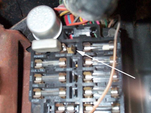
Notice the white arrow pointing to the master power wire tang. This
is the item that will have to be inserted from the back side of the fuse
box. This is the most common item missing when a PW set-up is removed from
a donor car. Also, notice the large master power fuse(to the left of the
tang.) This is another item commonly missed. You can get the master fuse
from most auto parts stores. The tang can be purchased from Radio Shack
and is called an in-line fuse holder.
 Here is the master power wire on the left that plugs onto
the tang above. The pink "turn on" wire goes to the fuse box marked
"ign" This wire does not have power until the key is moved to
the "on" position. This limits the pw to work only when the key
is on. The white arrow indicates the raised ridge on the plug so it can
only plug into "ign" fuse box sockets. If you want the windows
to work regardless of key position, you will need to change the plug to
one where you can plug it into the "bat" fuse box terminal which
is direclty below the master power wire tang in the pic above.
Here is the master power wire on the left that plugs onto
the tang above. The pink "turn on" wire goes to the fuse box marked
"ign" This wire does not have power until the key is moved to
the "on" position. This limits the pw to work only when the key
is on. The white arrow indicates the raised ridge on the plug so it can
only plug into "ign" fuse box sockets. If you want the windows
to work regardless of key position, you will need to change the plug to
one where you can plug it into the "bat" fuse box terminal which
is direclty below the master power wire tang in the pic above.
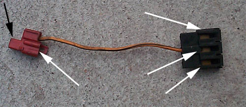 Here is a the master power splitter. The red connector plugs
on the master fuse tang(black arrow.) The white arrows on the right show
the three sockets for other power options. These would be for PW, PDL, PSeat.
Also, notice the white arrow on the red connector. This socket would be
for convertible power tops or another power accessory such as power trunk.
Here is a the master power splitter. The red connector plugs
on the master fuse tang(black arrow.) The white arrows on the right show
the three sockets for other power options. These would be for PW, PDL, PSeat.
Also, notice the white arrow on the red connector. This socket would be
for convertible power tops or another power accessory such as power trunk.
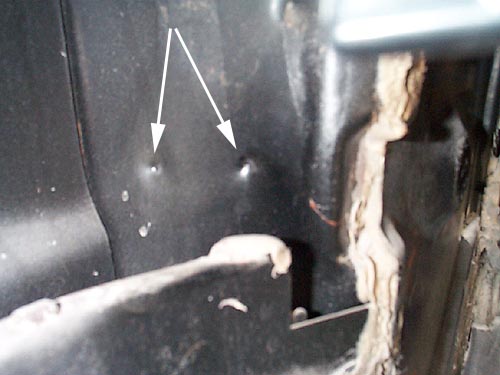 This is the view inside the driver's side kick panel. Two
dimples indicate the location for the PW relay. Use a 1/8" drill to
make two holes for sheet metal screws.
This is the view inside the driver's side kick panel. Two
dimples indicate the location for the PW relay. Use a 1/8" drill to
make two holes for sheet metal screws.
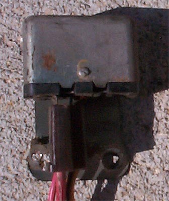 This is the PW relay that mounts inside the driver's kick
panel. The pink "turn on" wire activates this relay to allow power
from the fuse box master power tang to the PW wiring harness.
This is the PW relay that mounts inside the driver's kick
panel. The pink "turn on" wire activates this relay to allow power
from the fuse box master power tang to the PW wiring harness.
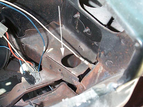
 This is the view of the driver's side cowl. Notice 3 dimples.
The center dimple locates the opening for the flexible boot. The other two
are the plastic retainer pins that hold the boot to the cowl. The main hole
is 2.25" and the retainer pin holes are 1/8". Use a door hole
saw for the 2.25" opening. These are available at home centers and
one will be pictured below. Use some WD40, PB Blaster or Liquid Wrench to
lubricate the hole saw which will keep it cool and reduce friction. The
door hole saws are made for wood but will work on metal if you keep drill
rpms low. Take your time and place light pressure on the drill to prevent
the cutting teeth from becoming dull.
This is the view of the driver's side cowl. Notice 3 dimples.
The center dimple locates the opening for the flexible boot. The other two
are the plastic retainer pins that hold the boot to the cowl. The main hole
is 2.25" and the retainer pin holes are 1/8". Use a door hole
saw for the 2.25" opening. These are available at home centers and
one will be pictured below. Use some WD40, PB Blaster or Liquid Wrench to
lubricate the hole saw which will keep it cool and reduce friction. The
door hole saws are made for wood but will work on metal if you keep drill
rpms low. Take your time and place light pressure on the drill to prevent
the cutting teeth from becoming dull.
 Here are the same set of dimples on the door. Use a 2"
door hole saw for the main hole. 1/8" for the other as stated above.
Here are the same set of dimples on the door. Use a 2"
door hole saw for the main hole. 1/8" for the other as stated above.
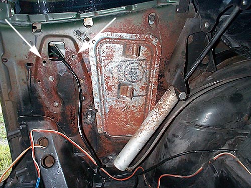
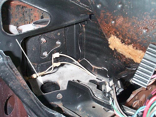 This view shows the driver's side cowl with the instrument
cluster removed from a 70 GS455. Notice the lower left corner. This is the
hole just drilled in the cowl for the flexible boot. The arrow indicates
the routing of the cowl wiring harness that connects the driver's side to
the pass. side wiring harness. Also, directly below the arrow is the location
for the relay previously pictured.
This view shows the driver's side cowl with the instrument
cluster removed from a 70 GS455. Notice the lower left corner. This is the
hole just drilled in the cowl for the flexible boot. The arrow indicates
the routing of the cowl wiring harness that connects the driver's side to
the pass. side wiring harness. Also, directly below the arrow is the location
for the relay previously pictured.
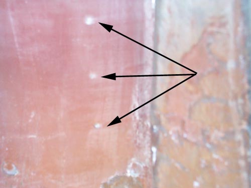
 Here is a pic of the firewall from the pass. compartment.
Notice the white arrows pointing to each side of the front defrost duct.
The cowl harness must pass behind the duct and is held in place by small
plastic wire holders. There are appoximate 4 of them attached to the cowl
using sheet metal screws.
Here is a pic of the firewall from the pass. compartment.
Notice the white arrows pointing to each side of the front defrost duct.
The cowl harness must pass behind the duct and is held in place by small
plastic wire holders. There are appoximate 4 of them attached to the cowl
using sheet metal screws.
 Here is a pic of the plastic wiring harness clips.
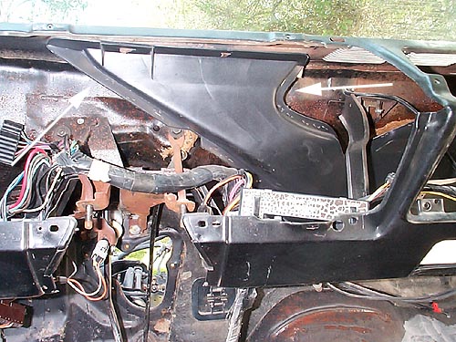
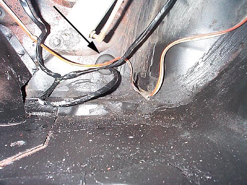
 Here is a pic of the pass. side cowl. The arrow indicates
where the pass. door wiring harness enters the cowl from the flexible boot
and bends upward to connect to the cowl wiring harness.
Here is a pic of the pass. side cowl. The arrow indicates
where the pass. door wiring harness enters the cowl from the flexible boot
and bends upward to connect to the cowl wiring harness.
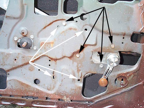 This is the driver's door w/the manual set-up still installed.
The easiest way to do the conversion is to have an assistant hold the glass
in the up position as you remove the screws indicated by black arrows. Make
sure you mask off the opening where you will slide out the manual mechanism
since the stamped steel edges are very sharp. Notice the manual crank handle
position. The master PW switch will be located in the same position. The
white arrows indicate where the PW regulator screws will be when you install
it. Make sure you lubricate all tracks and rollers with grease to ensure
smooth PW operation.
This is the driver's door w/the manual set-up still installed.
The easiest way to do the conversion is to have an assistant hold the glass
in the up position as you remove the screws indicated by black arrows. Make
sure you mask off the opening where you will slide out the manual mechanism
since the stamped steel edges are very sharp. Notice the manual crank handle
position. The master PW switch will be located in the same position. The
white arrows indicate where the PW regulator screws will be when you install
it. Make sure you lubricate all tracks and rollers with grease to ensure
smooth PW operation.
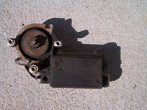
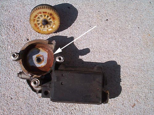 This is a 34+ year old pw motor. Notice how the factory grease
has hardened. Remove all old grease and replace with fresh grease. Reattach
to regulator and then slide the entire assembly inside door or rear panel.
Make sure regulator's roller slides into window channel and then line up
mounting screw nuts with mounting screw holes.
This is a 34+ year old pw motor. Notice how the factory grease
has hardened. Remove all old grease and replace with fresh grease. Reattach
to regulator and then slide the entire assembly inside door or rear panel.
Make sure regulator's roller slides into window channel and then line up
mounting screw nuts with mounting screw holes.
 Here is the rear side of a 70 conv. The black arrows indicate
the screws to be removed in order to remove the manual regulator. Have an
assistant hold the window up while you slide out the regulator. For convertibles,
notice the panel with USS on it. This panel needs to be removed in order
to slide out the regulator. Coupes do not have this panel.
Here is the rear side of a 70 conv. The black arrows indicate
the screws to be removed in order to remove the manual regulator. Have an
assistant hold the window up while you slide out the regulator. For convertibles,
notice the panel with USS on it. This panel needs to be removed in order
to slide out the regulator. Coupes do not have this panel.
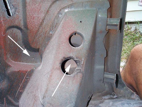 The white arrows indicate the holes for the lower PW regulator
screws. The screws are 1/4" diameter so use a 1/4" drill or slightly
larger to drill these two holes.
The white arrows indicate the holes for the lower PW regulator
screws. The screws are 1/4" diameter so use a 1/4" drill or slightly
larger to drill these two holes.
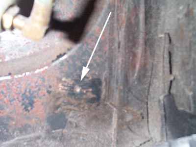 Here is the lower rear dimple for the wiring harness grommet.
This hole needs to be drilled with a hole saw. Diameter is 1.25"
Here is the lower rear dimple for the wiring harness grommet.
This hole needs to be drilled with a hole saw. Diameter is 1.25"
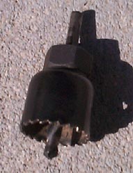 This is the door hole saw you can find at home centers. Made
for wood but works on metal if you keep drill rpm low and use some WD40,
PB Blaster, Liquid Wrench to keep the blade cool and helps lubricate cutting
teeth.
This is the door hole saw you can find at home centers. Made
for wood but works on metal if you keep drill rpm low and use some WD40,
PB Blaster, Liquid Wrench to keep the blade cool and helps lubricate cutting
teeth.
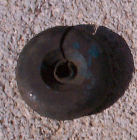 This is the rear wiring grommet. One per each rear window!
 Here is a comparison of early and later model switches. The
one on the upper right is early 1965-70. The lower left one is for 1971-1977.
Here is a comparison of early and later model switches. The
one on the upper right is early 1965-70. The lower left one is for 1971-1977.
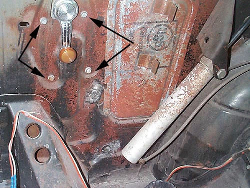
 Here is the completed installation on the passenger side
rear.
Notice the white arrows indicating the old manual regulator
position. The screw heads located a couple inches below are the new positions
for the power window regulator. These will have to be drilled. Once again,
position is indicated by a dimple.
Here is the completed installation on the passenger side
rear.
Notice the white arrows indicating the old manual regulator
position. The screw heads located a couple inches below are the new positions
for the power window regulator. These will have to be drilled. Once again,
position is indicated by a dimple.
 Here is the rear grommet discussed earlier.
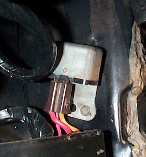 Here is the completed installation of the relay.