After doing the block oiling mods, I decided to take a crack at modding the front cover and oil filter adapter. The general idea is to do some smoothing, deburring of casting flash, removal of restrictions, and slight enlargement. I was able to first practice on some junk pieces. Take your time and don’t get carried away.
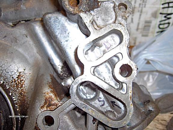
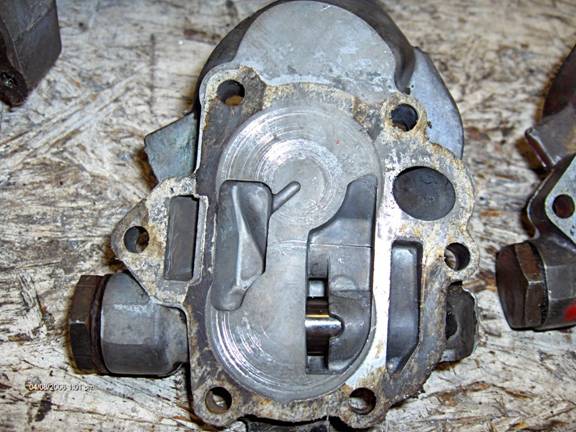
First, the front timing cover. The first photo (above) is of the backside of the front cover, with the pump downwards and the distributor hole upwards. The photo shows the suction (pump inlet, or “S”) passage at the bottom and discharge (pump outlet, or “D”) passage near the top. Here I used a carbide bur to smooth the rough edges where the passages make 90 degree turns to go down to the pump. In the discharge passage facing you, I ran a ½” drill bit in it to open it up a little; if you do this be sure to center the bit as it will try to “walk” and eat into the gasket sealing surfaces.
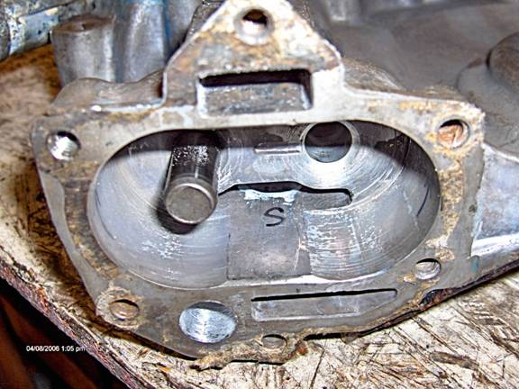
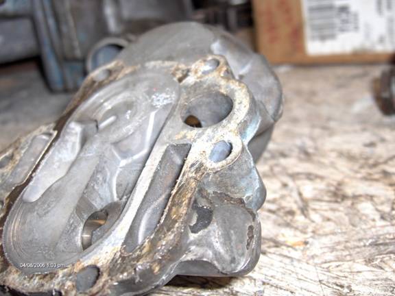
The next photo shows the gear pocket, the front cover is lying with the engine side down. The photo shows the gear pocket and pump inlet (just above the “S”). This is the other end (after a 90 deg turn) of the “S” inlet passage mentioned above. I just smoothed the 90 deg turns with a bur, trying not to enlarge it any in the downward (towards you) direction. The photo doesn’t show it, but there is room at the top of the passage to enlarge it slightly upwards.
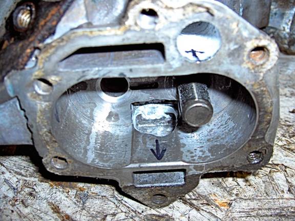
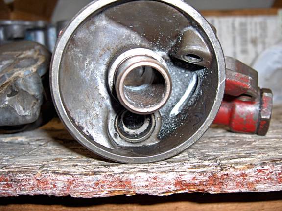
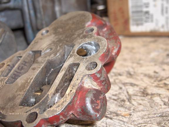
With the cover flipped over, this photo shows the discharge hole at the top of the pic (marked with the arrow inside, pointing away) which is the other end of the “D” passage shown in pic 1 (after the 90 deg turn). This hole was opened from .470” (stock) to .530” using a 17/32” drill bit. You will be able to see the far end of the bit through the discharge passage so you will know when to stop. The far end of this hole is where you will want to smooth the 90 deg turn. The outlet port of the pump which feeds oil to the filter adapter is in the middle of the picture, near the tail of the arrow pointing towards you. I opened up the hole towards the top using a bur, don’t make the hole any larger towards the bottom; that feature (along with the 90 deg. turns at the cover inlet and outlet) helps keep oil in the pump when the engine is off. Also be careful and don’t get into the gear surfaces to either side (left and right) of the hole.
Now, the oil filter adapter. Oil leaves the pump and enters the adapter through the rectangular slot at the left in the picture. Oil leaves the adapter and back into the cover through the round discharge hole (with the arrow inside) at the right. Not much to see from this top angle except where I enlarged the hole on the right to 17/32”. Be very careful as the filter bypass spring is at the bottom of this hole, stop before you get there. You will want to smooth out this hole with a bur where it intersects with another (shown later). Also the astute observer will notice that I got a little carried away and “poked through” the casting, in the relieved area near the discharge hole. I got a little greedy on my 1970 casting. The next photo shows a later casting (1976) which is different in this area; it has more “meat”.
This is an unmodified later model piece.
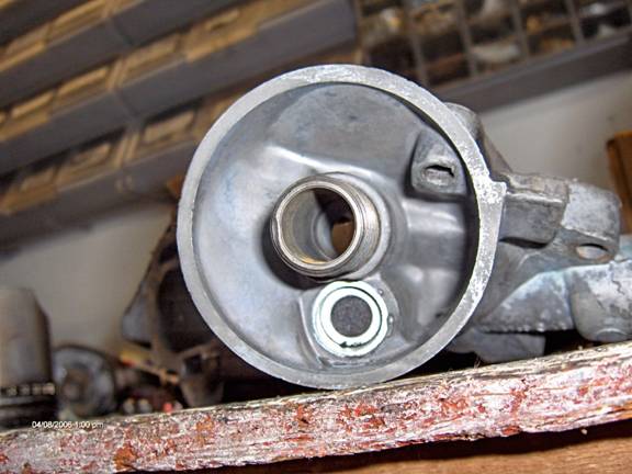
This next photo shows the adapter from the oil filter side where I just smoothed out the rectangular inlet’s rough edges and casting flash. The shiny metal is visible on the right.
Oil leaves the filter through the bigger round hole in the center, above the filter bypass valve. This photo shows where I smoothed the internal passage using a bur. There are a lot of jagged places and restrictions so just smooth those out and don’t get carried away here. You can also do some smoothing from the gear surface side of the adapter where the two holes intersect; be careful of the bypass spring at the far end of the bigger center hole.
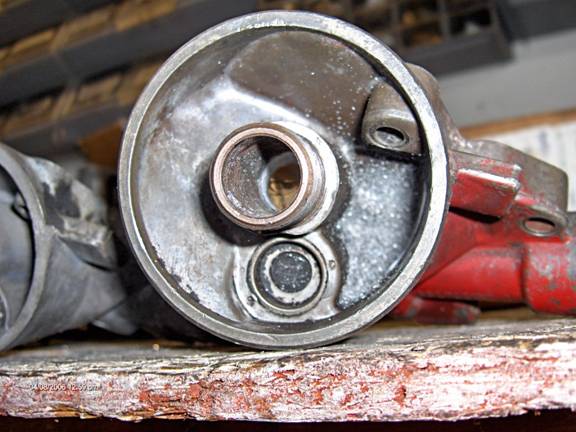
This picture shows a stock piece, showing the same hole with more restriction.
A view of the discharge hole porting from the gear side. The oil filter’s center big hole is at the far end of this one. Stop your porting as you near the gasket surface.
Same view, stock piece, more restriction.
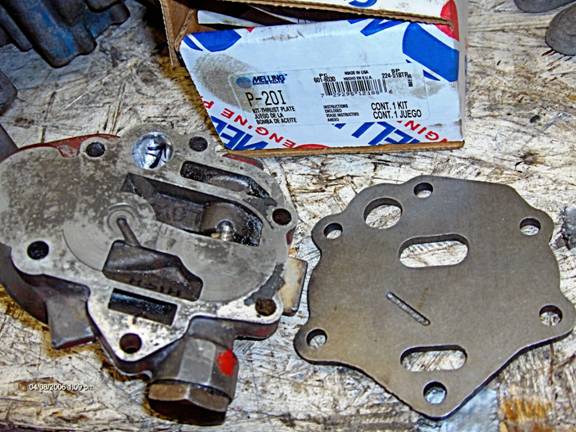
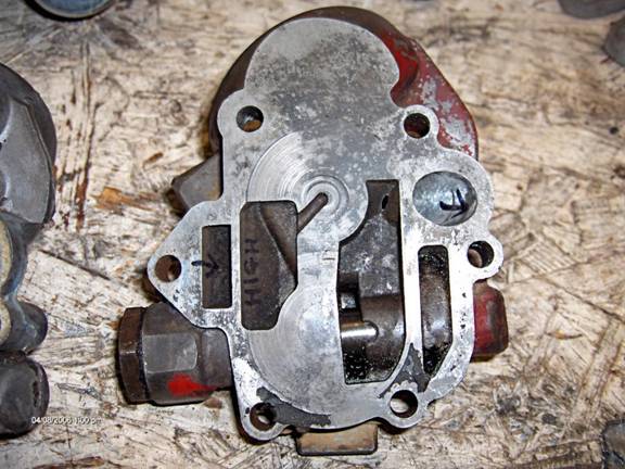
A word on oil booster plates. This is a photo of my Melling P-20I plate. In addition to a new wear surface for the gears, it increases the efficiency of the pump by decreasing the pumping losses. It works like this: it “closes off” the relieved area of the adapter, on which the gears ride as they turn, carrying oil from the low pressure side around to the high pressure side. In the photo, you might be able to make out the “low” and “high” written in the relieved areas. The gear on the left turns counterclockwise, the right gear turns clockwise. In the relieved area, any oil that the gears are trying to compress “squirts back” down into the suction (low pressure) area, instead of being carried on around. Only where the area is completely closed off can the pump develop pressure and move oil. You can see from the pic of the stock adapter that the left gear turns about halfway through a revolution that is useful. The right gear about ¼ of a turn. The booster plate closes off these relieved areas so that more of the oil is carried around by the gears and is not wasted. Now looking at the gear pocket in the front cover, you’ll see that the gears are not completely “surrounded” plus at the top there is an area where it is also open, so the plate only helps out on the filter adapter’s inefficiencies, but it helps. Make sure the bigger round hole in the booster plate as well as the oval slot at the bottom do not obstruct flow in either the adapter or the cover; you might have to “port match”. The round hole measured .600”, the slot needed a little clearancing at the corners to fit mine. The larger oval slot is to allow excess oil from the pressure relief valve to be allowed back into the suction side.